Radial Leaded Reset Dip PTC Resettable Fuse 265VDC 80mA For Line Voltage Transformers
Description Of Reset Dip PTC Resettable Fuse 265VDC
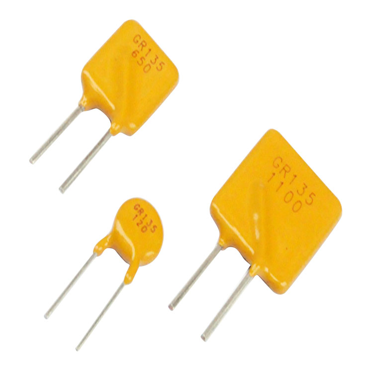
A range of radially-wired PTC Resettable Fuse with operation up to 265V rms, designed for Line Voltage Power Supplies, Transformers and Other Electrical Products.
Features Of Reset Dip PTC Resettable Fuse 265VDC
Low Operating Current
Radial Leaded PackageSuitable For Circuit Protection Below 265VdcWide range of operating current levels 0.02A~2AMaximum Working Voltage: 265VDCOperating Temperature Range: -40°C To 85°CLead-Free, Halogen-Free Environmentally Friendly Products That Meet RoHS And REACH StandardsSafety Certification: UL, CUL
Designed for general purpose over-current, overvoltage and direct over-temperature protection
Excellent stability
Fail-safe operation
Solid state
High performance encapsulation
Suitable for automatic PCB insertion
Electrical Characteristics at 25℃ Of The Dip PTC Resettable Fuse 265VDC
|
P/N
|
IH
(A)
|
IT
(A)
|
Umax
(V)
|
Imax
(A)
|
Pdtyp
(W)
|
Max.Time-to-trip
|
Rmin
(Ω)
|
Rmax
(Ω)
|
R1max
(Ω)
|
|
(A)
|
(S)
|
|
GR265-020
|
0.02
|
0.04
|
265
|
1.0
|
0.6
|
0.10
|
8.0
|
60.0
|
150.0
|
200.0
|
|
GR265-030
|
0.03
|
0.06
|
265
|
1.0
|
0.6
|
0.15
|
5.0
|
35.0
|
90.0
|
120.0
|
|
GR265-040
|
0.04
|
0.08
|
265
|
1.0
|
0.7
|
0.20
|
6.0
|
25.0
|
65.0
|
90.0
|
|
GR265-050
|
0.05
|
0.10
|
265
|
1.0
|
0.7
|
0.25
|
5.0
|
22.0
|
55.0
|
75.0
|
|
GR265-060
|
0.06
|
0.12
|
265
|
1.2
|
0.8
|
0.30
|
5.0
|
18.0
|
45.0
|
60.0
|
|
GR265-080
|
0.08
|
0.16
|
265
|
1.2
|
0.8
|
0.40
|
5.0
|
11.0
|
22.0
|
33.0
|
|
GR265-120C
|
0.12
|
0.24
|
265
|
1.2
|
1.0
|
0.60
|
5.0
|
6.0
|
12.0
|
16.0
|
|
GR265-120S
|
0.12
|
0.24
|
265
|
1.2
|
1.0
|
0.60
|
5.0
|
6.0
|
12.0
|
16.0
|
|
GR265-160
|
0.16
|
0.32
|
265
|
2.0
|
1.4
|
0.80
|
15.0
|
3.5
|
7.8
|
10.4
|
|
GR265-200C
|
0.20
|
0.40
|
265
|
3.0
|
1.5
|
1.00
|
9.0
|
3.0
|
6.5
|
8.0
|
|
GR265-200S
|
0.20
|
0.40
|
265
|
3.0
|
1.5
|
1.00
|
9.0
|
3.0
|
6.5
|
8.0
|
|
GR265-250
|
0.25
|
0.50
|
265
|
3.5
|
1.5
|
1.25
|
7.0
|
2.2
|
5.0
|
6.0
|
|
GR265-300
|
0.30
|
0.60
|
265
|
4.5
|
1.7
|
1.50
|
8.0
|
1.8
|
4.0
|
4.8
|
|
GR265-330
|
0.33
|
0.66
|
265
|
4.5
|
1.7
|
1.65
|
8.0
|
1.6
|
3.6
|
4.3
|
|
GR265-400
|
0.40
|
0.80
|
265
|
5.5
|
2.0
|
2.00
|
9.0
|
1.35
|
3.0
|
3.6
|
|
GR265-500
|
0.50
|
1.0
|
265
|
6.5
|
2.5
|
2.50
|
10.0
|
0.90
|
2.00
|
2.4
|
|
GR265-550
|
0.55
|
1.1
|
265
|
7.0
|
2.5
|
2.75
|
9.0
|
0.80
|
1.65
|
2.0
|
|
GR265-600
|
0.60
|
1.2
|
265
|
6.0
|
2.5
|
3.00
|
8.0
|
0.75
|
1.50
|
1.8
|
|
GR265-650
|
0.65
|
1.3
|
265
|
6.5
|
2.6
|
3.25
|
12.0
|
0.65
|
1.30
|
1.6
|
|
GR265-750
|
0.75
|
1.5
|
265
|
7.5
|
2.6
|
3.75
|
18.0
|
0.55
|
1.10
|
1.3
|
|
GR265-800
|
0.80
|
1.6
|
265
|
8.0
|
2.7
|
4.00
|
18.0
|
0.50
|
1.00
|
1.2
|
|
GR265-900
|
0.90
|
1.8
|
265
|
9.0
|
2.8
|
4.50
|
18.0
|
0.45
|
0.90
|
1.1
|
|
GR265-1000C
|
1.00
|
2.0
|
265
|
10.0
|
2.9
|
5.00
|
21.0
|
0.37
|
0.75
|
0.90
|
|
GR265-1000S
|
1.00
|
2.0
|
265
|
10.0
|
2.9
|
5.00
|
21.0
|
0.37
|
0.75
|
0.90
|
|
GR265-1100
|
1.10
|
2.2
|
265
|
10.0
|
3.1
|
5.50
|
21.0
|
0.33
|
0.66
|
0.80
|
|
GR265-1250C
|
1.25
|
2.5
|
265
|
10.0
|
3.3
|
6.25
|
23.0
|
0.27
|
0.55
|
0.66
|
|
GR265-1250S
|
1.25
|
2.5
|
265
|
10.0
|
3.3
|
6.25
|
23.0
|
0.27
|
0.55
|
0.66
|
|
GR265-1350
|
1.35
|
2.7
|
265
|
10.0
|
3.5
|
6.75
|
23.0
|
0.25
|
0.50
|
0.60
|
|
GR265-1600
|
1.60
|
3.2
|
265
|
10.0
|
3.9
|
8.00
|
23.0
|
0.20
|
0.40
|
0.48
|
|
GR265-1850
|
1.85
|
3.7
|
265
|
10.0
|
4.3
|
9.25
|
23.0
|
0.165
|
0.33
|
0.40
|
|
GR265-2000
|
2.00
|
4.0
|
265
|
10.0
|
4.5
|
10.00
|
28.0
|
0.135
|
0.27
|
0.33
|
Size Of Reset Dip PTC Resettable Fuse 265VDC in mm
|
Part Number
|
A
|
B
|
C
|
D
|
Diameter
|
Shape
|
|
GR265-020
|
6.0
|
8.7
|
5.1±0.5
|
4.6
|
0.5
|
F5
|
|
GR265-030
|
6.0
|
8.7
|
5.1±0.5
|
4.6
|
0.5
|
F5
|
|
GR265-040
|
6.0
|
9.3
|
5.1±0.5
|
4.6
|
0.5
|
F5
|
|
GR265-050
|
6.0
|
9.3
|
5.1±0.5
|
4.6
|
0.5
|
F5
|
|
GR265-060
|
6.0
|
10.0
|
5.1±0.5
|
4.6
|
0.6
|
F2
|
|
GR265-080
|
6.0
|
10.0
|
5.1±0.5
|
4.6
|
0.6
|
F5
|
|
GR265-120C
|
7.2
|
11.2
|
5.1±0.5
|
4.6
|
0.6
|
F5
|
|
GR265-120S
|
6.5
|
10.5
|
5.1±0.5
|
4.6
|
0.6
|
F6
|
|
GR265-160
|
9.3
|
12.8
|
5.1±0.5
|
4.6
|
0.6
|
F5
|
|
GR265-200C
|
10.0
|
13.5
|
5.1±0.5
|
4.6
|
0.6
|
F5
|
|
GR265-200S
|
9.3
|
12.8
|
5.1±0.5
|
4.6
|
0.6
|
F6
|
|
GR265-250
|
9.3
|
12.8
|
5.1±0.5
|
4.6
|
0.6
|
F6
|
|
GR265-300
|
9.3
|
14.5
|
5.1±0.5
|
4.6
|
0.6
|
F6
|
|
GR265-330
|
9.3
|
14.5
|
5.1±0.5
|
4.6
|
0.6
|
F6
|
|
GR265-400
|
10.5
|
16.5
|
5.1±0.5
|
4.6
|
0.8
|
F4
|
|
GR265-500
|
11.8
|
17.5
|
5.1±0.5
|
4.6
|
0.8
|
F4
|
|
GR265-550
|
11.8
|
17.5
|
5.1±0.5
|
4.6
|
0.8
|
F4
|
|
GR265-600
|
11.8
|
17.5
|
5.1±0.5
|
4.6
|
0.8
|
F4
|
|
GR265-650
|
14.0
|
18.8
|
5.1±0.5
|
4.6
|
0.8
|
F4
|
|
GR265-750
|
14.5
|
22.2
|
5.1±0.5
|
4.6
|
0.8
|
F4
|
|
GR265-800
|
14.5
|
22.2
|
5.1±0.5
|
4.6
|
0.8
|
F4
|
|
GR265-900
|
16.5
|
24.5
|
10.2±0.5
|
4.6
|
0.8
|
F4
|
|
GR265-1000C
|
21.1
|
25.1
|
10.2±0.5
|
4.6
|
0.8
|
F2
|
|
GR265-1000S
|
19.0
|
25.5
|
10.2±0.5
|
4.6
|
0.8
|
F4
|
|
GR265-1100
|
19.0
|
25.5
|
10.2±0.5
|
4.6
|
0.8
|
F4
|
|
GR265-1250C
|
24.2
|
28.2
|
10.2±0.5
|
4.6
|
0.8
|
F2
|
|
GR265-1250S
|
19.0
|
29.0
|
10.2±0.5
|
4.6
|
0.8
|
F4
|
|
GR265-1350
|
19.0
|
29.0
|
10.2±0.5
|
4.6
|
0.8
|
F4
|
|
GR265-1600
|
21.5
|
29.0
|
10.2±0.5
|
4.6
|
0.8
|
F4
|
|
GR265-1850
|
25.0
|
29.0
|
10.2±0.5
|
4.6
|
0.8
|
F4
|
|
GR265-2000
|
25.0
|
33.5
|
10.2±0.5
|
4.6
|
0.8
|
F4
|
Physical Properties Of Reset Dip PTC Resettable Fuse 265VDC
Lead material: tinned wire.
Welding specification: Welding capacity adopts ANSI / J-STD-002 category 3.
Resistance to soldering heat: Test Tb using IEC-STD 68-2-20, method 1a, condition a or b, can withstand 5 seconds or 10 seconds at 260 ℃ ± 5 ℃.
Encapsulation material: Cured flame retardant epoxy resin, in line with UL-94V-0 specifications.
Fuse or PTC Resettable Fuse - Protecting against overcurrent incidents ?
When it comes to overcurrent protection of electronic equipment, fuses have long been the standard solution. They come in a wide variety of ratings and mounting styles to fit virtually any application.
When they open, they completely stop the flow of electricity, which may be the desired reaction. The equipment or circuit is rendered inoperable, which draws the user’s attention to what may have caused the overload condition so that corrective action can be taken.
Nevertheless, there are circumstances and circuits where auto recovery from a temporary overload without user intervention is desirable. Positive temperature coefficient (PTC)thermistors — also called resettable fuses or polymeric positive temperature coefficient devices (PPTCs) — are an excellent way of achieving this type of protection.
How a PTC works
A PTC consists of a piece of polymer material loaded with conductive particles (usually carbon black). At room temperature the polymer is in a semi crystalline state and the conductive particles touch each other, forming multiple conductive paths and providing low resistance (generally about twice that of a fuse of the same rating).
When current passes through the PTC it dissipates power (P = I2R) and its temperature increases. As long as the current is less than its rated hold current (Ihold), the PTC will remain in a low-resistance state and the circuit will operate normally.
When the current exceeds the rated trip current(Itrip), the PTC heats up suddenly. The polymer changes to an amorphous state and expands, breaking the connections between the conductive particles.
This causes the resistance to increase rapidly by several orders of magnitude and reduces the current to a low(leakage) value just sufficient to keep the PTC in the high-resistance state — generally from around tens to several hundred milliamps at rated voltage (Vmax). When the power is shut off the device cools down and returns to its low-resistance state.
PTC and fuse parameters
Like a fuse, a PTC is rated for the maximum short-circuit current (Imax) it can interrupt at rated voltage. Imax for a typical PTC is 40 A, and may reach 100 A. Interrupt ratings for fuses of the sizes that may be used in the sorts of applications we are considering here can range from 35 to 10,000 A at rated voltage.
The voltage rating for a PTC is limited. PTCs for general use are not rated above 60 V (there are PTCs for telecom application with 250 and 600 V interrupting voltage, but their operating voltage is still 60 V); SMT and small-cartridge fuses are available with ratings from 32 to 250 V or more.
The operating current rating for PTCs ranges to about 9 A, while the maximum level for fuses of the types considered here can exceed 20 A, with some available to 60 A.
The useful upper temperature limit for a PTC is generally 85C, while the maximum operating temperature for thin-film SMT fuses is 90C, and for small-cartridge fuses is 125C.Both PTCs and fuses require derating for temperatures above 20C,although PTCs are more sensitive to temperature.
When designing in any overcurrent protective device, be sure to consider factors that may affect its operating temperature, including the effect on heat removal of leads/traces ,any air flow, and proximity to heat sources. The speed of response for a PTC is similar to that of a time-delay fuse.
Common PTC applications
Much of the design work for personal computers and peripheral devices is strongly influenced by the Microsoft and Intel System Design Guide which states that “Using a fuse that must be replaced each time an overcurrent condition occurs is unacceptable.” And, the SCSI Standard for this large market includes a statement that “....a positive temperature coefficient device must be used instead of a fuse, to limit the maximum amount of current sourced.”
PTCs are used to provide secondary overcurrent protection for telephone central office equipment, customer premises equipment, alarm systems, set-top boxes, VOIP equipment, and subscriber line interface circuits. They provide primary protection for battery packs, battery chargers, automotive door locks, USB ports, loudspeakers, and PoE.
SCSI plug-and-play applications that benefit from PTCs include the motherboard and the many peripherals that can be frequently connected to and disconnected from the computer ports. The mouse, keyboard, printer, modem, and monitor ports represent opportunities for misconnections, and connections of faulty units or damaged cable. The ability to reset after correction of the fault is particularly attractive.
A PTC can protect disk drives from the potentially damaging overcurrents resulting from excessive current from a power supply malfunction. PTCs can protect power supplies against overloading; individual PTCs can be placed in the output circuits to protect each load where there are multiple loads or circuits.
Motor overcurrents can produce excessive heatthat may damage the winding insulation and for small motors may even cause a failure of the very small diameter wire windings. The PTC will generally not trip under normal motor start up currents, but will act to prevent a sustained overload from causing damage.
Transformers can be damaged by overcurrents caused by circuit faults, and the current limiting function of a PTC can provide protection. The PTC is located on the load side of the transformer.
Fuse or PTC?
The following procedure will help in selecting and applying the correct component. Help is also available from device suppliers. For unbiased advice it’s wise to look for a company that offers both fuse and PTC technology.
1. Define the circuit operating parameters taking into consideration:
Normal operating current in amperes
Normal operating voltage in volts
Maximum interrupt current
Ambient temperature/rerating
Typical overload current
Required opening time at specific overload
Transient pulses expected
Resettable or one-time
Agency Approvals
Mounting type/form factor
Typical resistance (in circuit):
2. Select a prospective circuit protection component (See table)
3. Consult the time-current (T-C) curve to determine if the selected part will operate within the constraints of the application.
4. Ensure that the application voltage is less than or equal to the device’s rated voltage and that the operating temperature limits are within those specified by the device. If using a PTC, thermally derate Ihold using the equation below.
Ihold =derated Ihold
Thermal derating factor
5. Compare the maximum dimensions of the device to the space available in the application.
|
Overcurrent Selection Guide (typical values)
|
|
|
Surface Mount PTC
|
60-V PTC, Leaded
|
Surface Mount Fuse
|
3AG/3AB Fuse
|
2AG Fuse
|
5x20 Fuse
|
|
Operating current range (A)
|
0.05 to 3.0
|
0.100 to 3.75
|
0.062 to 30
|
0.010 to 35
|
0.10 to 10
|
0.032 to 15
|
|
Max Voltage (V)
|
60
|
60
|
125
|
250
|
250*
|
250
|
|
Max Interrupting Rating (A)
|
100
|
40
|
100
|
10,000
|
10,000
|
10,000
|
|
Temperature Range (C)
|
–40 to 85
|
–40 to 85
|
–55 to 90
|
–55 to 125
|
–55 to 125
|
–55 to 125
|
|
Thermal Rerating
|
High
|
High
|
Medium
|
Low
|
Low
|
Low
|
|
Operating time at 200%
|
Slow
|
Slow
|
Fast
|
Fast to Slow
|
Fast to Slow
|
Fast to Slow
|
|
Transient Withstand
|
Low
|
Low
|
Low
|
Low to High
|
Low to High
|
Low to High
|
|
Resistance
|
Medium
|
Medium
|
Medium
|
Low
|
Low
|
Low
|
|
Operational Uses
|
Multiple
|
Multiple
|
One Time
|
One Time
|
One Time
|
One Time
|
|
Mounting/Form Factor
|
SMT
|
Leaded SMT
|
Leaded or Cartridge
|
Leaded or Cartridge
|
Leaded or Cartridge
|
Leaded or Cartridge
|
|
* Special 350-V units also available
|
Hot Tags: Reset Dip PTC Resettable Fuse, China, Manufacturers, Suppliers, Factory, Made in China, Wholesale, Buy, Customized, in stock, Bulk, Free Sample, Cheap, Discount, Buy discount, Low price, Price, Price list, Quotation
 English
  Español
  Português
  русский
  Français
  日本語
日本語  Deutsch
  tiếng Việt
  Italiano
  Nederlands
  ภาษาไทย
  Polski
  한국어
한국어  Svenska
  magyar
  Malay
Malay  বাংলা ভাষার
  Dansk
Dansk  Suomi
Suomi  हिन्दी
  Pilipino
  Türkçe
  Gaeilge
  العربية
  Indonesia
  Norsk
Norsk  تمل
تمل  český
český  ελληνικά
  український
  Javanese
  فارسی
فارسی  தமிழ்
தமிழ்  తెలుగు
  नेपाली
  Burmese
  български
  ລາວ
ລາວ  Latine
  Қазақша
  Euskal
  Azərbaycan
  Slovenský jazyk
  Македонски
  Lietuvos
  Eesti Keel
  Română
  Slovenski
  मराठी
मराठी  Srpski језик


