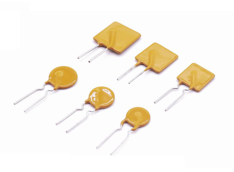
Radial Leaded Polymeric Dip PTC Resettable Fuse
Radial Leaded Through Hole Poly Switch Polymeric Dip PTC Resettable Fuse 30V
The Dip PTC Resettable Fuse 30V is designed to provide overcurrent protection for low voltage (≤30V) applications where space is not a concern and resettable protection is preferred.
Features Of Radial Leaded Polymeric Dip PTC Resettable Fuse 30V
Cured, flame retardant epoxy polymer insulating material meets UL 94V-0 requirements
Fast time–to-trip
RoHS compliant, Lead-Free and Halogen-Free
New Low Resistance PolySwitch Resettable PTCs Now AvailableRadial Leaded Devices
Bulk Package, or tape andreelavailable on most models
A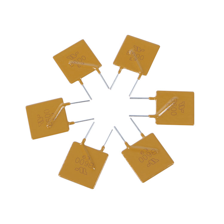
Application Of Radial Leaded Polymeric Dip PTC Resettable Fuse 30V
Almost anywhere there is a low voltage
power supply, up to 30V and a load to be
protected, including:
Personal computer
Toys
Industrial controls
USB hubs, ports and peripherals
Computers & peripherals
Motor protection
General electronics
Automotive applications
Electrical Characteristics Of Radial Leaded Polymeric Dip PTC Resettable Fuse 30V
|
P/N
|
Hold Current
|
Trip Current
|
Max Current
|
Max Current
|
Max Voltage
|
Max Trip Time
|
Power consumption
|
|
IH, (A)
|
IT,(A)
|
Vmax,(v)
|
Imax,(A)
|
(A)
|
(Sec.)
|
Pdtyp(W)
|
Rmin
|
Rmax
|
R1max
|
|
TRB090
|
0.90
|
1.80
|
30
|
40
|
4.50
|
5.9
|
0.60
|
0.090
|
0.230
|
0.300
|
|
TRB110
|
1.10
|
2.20
|
30
|
40
|
5.50
|
6.6
|
0.70
|
0.060
|
0.160
|
0.260
|
|
TRB120
|
1.20
|
2.40
|
30
|
40
|
6.00
|
6.5
|
0.70
|
0.050
|
0.115
|
0.255
|
|
TRB135
|
1.35
|
2.70
|
30
|
40
|
6.75
|
7.3
|
0.80
|
0.040
|
0.095
|
0.170
|
|
TRB160
|
1.60
|
3.2
|
30
|
40
|
8.00
|
8.0
|
0.90
|
0.030
|
0.095
|
0.160
|
|
TRB185
|
1.85
|
3.7
|
30
|
40
|
9.25
|
8.7
|
1.00
|
0.030
|
0.070
|
0.110
|
|
TRB250
|
2.50
|
5.0
|
30
|
40
|
12.5
|
10.3
|
1.20
|
0.020
|
0.048
|
0.072
|
|
TRB300
|
3.00
|
6.00
|
30
|
40
|
15.0
|
10.8
|
2.00
|
0.015
|
0.050
|
0.075
|
|
TRB400
|
4.00
|
8.00
|
30
|
40
|
20.0
|
12.7
|
2.50
|
0.010
|
0.030
|
0.045
|
|
TRB500
|
5.00
|
10.00
|
30
|
40
|
25.0
|
14.5
|
3.00
|
0.008
|
0.025
|
0.045
|
|
TRB600
|
6.00
|
12.00
|
30
|
40
|
30.0
|
16.0
|
3.50
|
0.005
|
0.020
|
0.030
|
|
TRB700
|
7.00
|
14.00
|
30
|
40
|
35.0
|
17.5
|
3.80
|
0.003
|
0.016
|
0.025
|
|
TRB800
|
8.00
|
16.00
|
30
|
40
|
40.0
|
18.8
|
4.00
|
0.004
|
0.015
|
0.023
|
|
TRB900
|
9.00
|
18.00
|
30
|
40
|
40.0
|
20.0
|
4.00
|
0.004
|
0.010
|
0.015
|
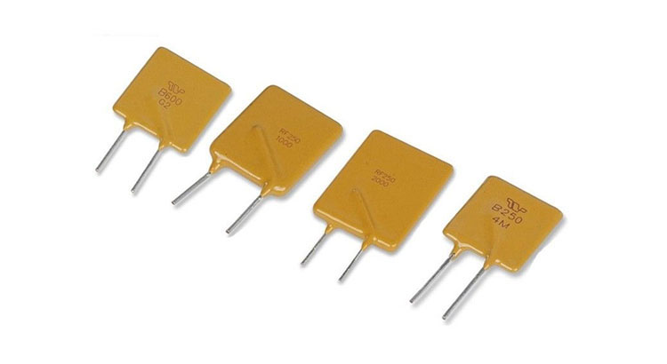
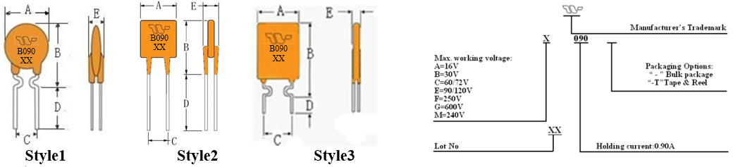
Product Dimensions & Marking Of Radial Leaded Polymeric Dip PTC Resettable Fuse 30V (Unit: mm)
|
P/N
|
A
|
B
|
C
|
D
|
E
|
Physical Characteristics
|
|
Max.
|
Max.
|
Typ.
|
Min.
|
Max.
|
Style
|
Lead Φ mm
|
Material
|
|
TRB090
|
7.4
|
12.2
|
5.1
|
7.6
|
3.1
|
3
|
0.50
|
CP
|
|
TRB110
|
10.7
|
16.7
|
5.1
|
7.6
|
3.1
|
1
|
0.50
|
CP
|
|
TRB120
|
10.7
|
16.7
|
5.1
|
7.6
|
3.1
|
1
|
0.50
|
CP
|
|
TRB135
|
10.7
|
16.7
|
5.1
|
7.6
|
3.1
|
1
|
0.50
|
CP
|
|
TRB160
|
11.0
|
16.8
|
5.1
|
7.6
|
3.1
|
1
|
0.60
|
CU
|
|
TRB185
|
11.5
|
17.9
|
5.1
|
7.6
|
3.1
|
1
|
0.60
|
CU
|
|
TRB250
|
13.0
|
18.3
|
5.1
|
7.6
|
3.1
|
2
|
0.60
|
CU
|
|
TRB300
|
13.0
|
18.3
|
5.1
|
7.6
|
3.1
|
2
|
0.81
|
CU
|
|
TRB400
|
16.4
|
24.8
|
5.1
|
7.6
|
3.1
|
2
|
0.81
|
CU
|
|
TRB500
|
21.3
|
26.4
|
10.2
|
7.6
|
3.1
|
2
|
0.81
|
CU
|
|
TRB600
|
20.8
|
29.8
|
10.2
|
7.6
|
3.1
|
2
|
0.81
|
CU
|
|
TRB700
|
20.8
|
29.8
|
10.2
|
7.6
|
3.1
|
2
|
0.81
|
CU
|
|
TRB800
|
24.2
|
32.9
|
10.2
|
7.6
|
3.1
|
2
|
0.81
|
CU
|
|
TRB900
|
24.2
|
32.9
|
10.2
|
7.6
|
3.1
|
2
|
0.81
|
CU
|
Thermal Derating Chart Of Radial Leaded Polymeric Dip PTC Resettable Fuse 30V – I hold (Amps)
|
P/N
|
Ambient Operating Temperature
|
|
-40℃
|
-20℃
|
0℃
|
25℃
|
40℃
|
50℃
|
60℃
|
70℃
|
85℃
|
|
TRB090
|
1.40
|
1.22
|
1.07
|
0.90
|
0.73
|
0.65
|
0.57
|
0.49
|
0.36
|
|
TRB110
|
1.60
|
1.43
|
1.27
|
1.10
|
0.91
|
0.85
|
0.75
|
0.67
|
0.57
|
|
TRB120
|
1.75
|
1.56
|
1.39
|
1.20
|
0.99
|
0.93
|
0.82
|
0.73
|
0.62
|
|
TRB135
|
1.96
|
1.76
|
1.55
|
1.35
|
1.12
|
1.04
|
0.92
|
0.82
|
0.70
|
|
TRB160
|
2.32
|
2.08
|
1.84
|
1.60
|
1.33
|
1.23
|
1.09
|
0.98
|
0.83
|
|
TRB185
|
2.68
|
2.41
|
2.13
|
1.85
|
1.54
|
1.42
|
1.26
|
1.13
|
0.96
|
|
TRB250
|
3.63
|
3.25
|
2.88
|
2.50
|
2.08
|
1.93
|
1.70
|
1.53
|
1.30
|
|
TRB300
|
4.35
|
3.90
|
3.45
|
3.00
|
2.49
|
2.31
|
2.04
|
1.83
|
1.56
|
|
TRB400
|
5.80
|
5.20
|
4.60
|
4.00
|
3.32
|
3.08
|
2.72
|
2.44
|
2.08
|
|
TRB500
|
7.25
|
6.50
|
5.75
|
5.00
|
4.15
|
3.85
|
3.40
|
3.05
|
2.60
|
|
TRB600
|
8.70
|
7.80
|
6.90
|
6.00
|
4.98
|
4.62
|
4.08
|
3.66
|
3.12
|
|
TRB700
|
10.10
|
9.10
|
8.05
|
7.00
|
5.81
|
5.39
|
4.76
|
4.27
|
3.64
|
|
TRB800
|
11.60
|
10.40
|
9.20
|
8.00
|
6.64
|
6.16
|
5.44
|
4.88
|
4.16
|
|
TRB900
|
13.00
|
11.70
|
10.30
|
9.00
|
7.47
|
6.93
|
6.12
|
5.49
|
4.68
|
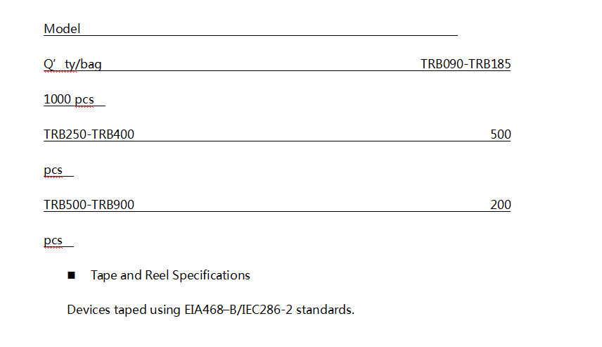
Package information Of Radial Leaded Polymeric Dip PTC Resettable Fuse 30V
Environmental Specifications Of Radial Leaded Polymeric Dip PTC Resettable Fuse 30V
|
Operating/Storage Temperature
|
-40°C to +85°C
|
|
Maximum Device Surface Temperature in Tripped State
|
125°C
|
|
Passive Aging
|
+85°C, 1000 hours -/+5% typical resistance change
|
|
Humidity Aging
|
+85°C, 85% R.H., 1000 hours -/+5% typical resistance change
|
|
Thermal Shock
|
+85°C to -40°C 10 times -/+5% typical resistance change
|
|
Solvent Resistance
|
MIL–STD–202, Method 215 No change
|
|
Moisture Resistance Level
|
Level 1, J–STD–020
|
Selection Process Of Radial Leaded Polymeric Dip PTC Resettable Fuse 30V
1. Determine the following circuit operating
parameters:
• Normal operating current – IHOLD
• Maximum circuit voltage – VMAX
• Maximum interrupt current – IMAX
• Ambient operating temperature
2. Select the suitable form factor.
3. Compare the PTC data sheet ratings for VMAX and IMAX to ensurethat the circuit parameters do not exceed these ratings. 4. Verify that the ambient operating temperature within close proximity to the device is within its normal operating range. Thermally derate IHOLD and IMAX as necessary. See equation below.
I HOLD = IMAX /Thermal derating factor
5. Check that the trip time protects the circuit.
6. Verify that the post trip resistance (R1MAX) of the device is taken into account in the
circuit design.
7. Independently test and evaluate the suitability and performance of the PTC in the actual application.
Hot Tags: Radial Leaded Polymeric Dip PTC Resettable Fuse, China, Manufacturers, Suppliers, Factory, Made in China, Wholesale, Buy, Customized, in stock, Bulk, Free Sample, Cheap, Discount, Buy discount, Low price, Price, Price list, Quotation
 English
  Español
  Português
  русский
  Français
  日本語
日本語  Deutsch
  tiếng Việt
  Italiano
  Nederlands
  ภาษาไทย
  Polski
  한국어
한국어  Svenska
  magyar
  Malay
Malay  বাংলা ভাষার
  Dansk
Dansk  Suomi
Suomi  हिन्दी
  Pilipino
  Türkçe
  Gaeilge
  العربية
  Indonesia
  Norsk
Norsk  تمل
تمل  český
český  ελληνικά
  український
  Javanese
  فارسی
فارسی  தமிழ்
தமிழ்  తెలుగు
  नेपाली
  Burmese
  български
  ລາວ
ລາວ  Latine
  Қазақша
  Euskal
  Azərbaycan
  Slovenský jazyk
  Македонски
  Lietuvos
  Eesti Keel
  Română
  Slovenski
  मराठी
मराठी  Srpski језик


